
Volvo V60 Plug-in Hybrid 2016 Fuse Box Info
Passenger compartment fuse box location:
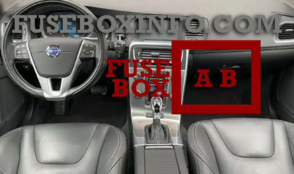
The fuse boxes in the passenger compartment are located under the glove box.
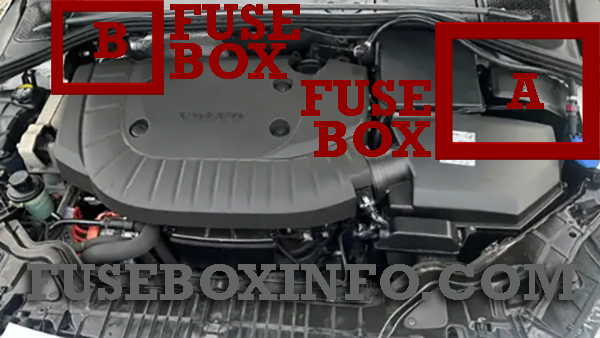
Engine compartment fuse box location:
Luggage compartment fuse box location:
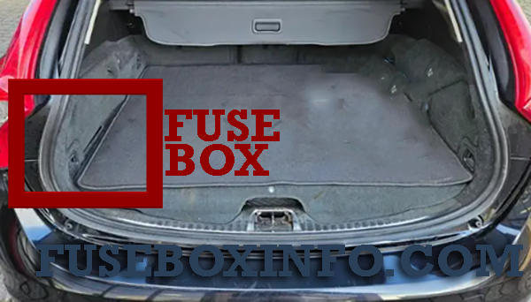
The fuse boxes are located behind the upholstery on the left-hand side.
Fuse Box Diagram | Layout
Passenger compartment fuse box A:
* Option/accessory
Passenger compartment fuse box B:
| Fuse/Relay N° | Rating | Functions |
| 1 | 15A | Rear window wiper |
| 2 | - | - |
| 3 | 7.5A | Interior lighting; Driver's door control panel, power windows; Power seats* |
| 4 | 5A | Combined instrument panel |
| 5 | 10A | Adaptive cruise control, ACC*; collision warning system* |
| 6 | 7.5A | Interior lighting; Rain sensor* |
| 7 | 7.5A | Steering wheel module |
| 8 | 10A | Central locking system, fuel filler flap |
| 9 | 15A | Heated steering wheel* |
| 10 | 15A | Heated windscreen* |
| 11 | 10A | Unlocking, tailgate |
| 12 | 10A | Folding head restraint* |
| 13 | 20A | Fuel pump |
| 14 | 5A | Movement detector alarm*; Climate panel |
| 15 | 15A | Steering lock |
| 16 | 5A | Siren*; Data link connector OBDII |
| 17 | - | - |
| 18 | 10A | Airbags |
| 19 | 5A | Collision warning system* |
| 20 | 7.5A | Accelerator pedal sensor; Dimming interior rearview mirror*; Seat heating, rear* |
| 21 | 15A | Infotainment control module (Performance); Audio (Performance) |
| 22 | 5A | Brake light |
| 23 | 20A | Sunroof* |
| 24 | 5A | Immobiliser |
* Option/accessory
Engine compartment fuse box A:
| Fuse/Relay N° | Rating | Functions |
| 1 | - | - |
| 2 | 50A | Primary fuse for the central electronic module (CEM) under the glovebox |
| 3 | - | - |
| 4 | 60A | Primary fuse for relay/fuse box under the glovebox |
| 5 | - | - |
| 6 | - | - |
| 7 | - | - |
| 8 | - | - |
| 9 | 30A | Windscreen wipers |
| 10 | 25A | Parking heater* |
| 11 | - | - |
| 12 | - | - |
| 13 | 40A | ABS pump |
| 14 | 20A | ABS valves |
| 15 | 20A | Headlamp washers* |
| 16 | 10A | Headlamp levelling*; Active Xenon headlamps - ABL* |
| 17 | 20A | Primary fuse for the central electronic module (CEM) under the glovebox |
| 18 | 5A | ABS |
| 19 | 5A | Adjustable steering force* |
| 20 | 10A | Engine control module; Transmission control module; Airbags |
| 21 | 10A | Heated washer nozzles* |
| 22 | - | - |
| 23 | 5A | Headlamp control |
| 24 | - | - |
| 25 | - | - |
| 26 | - | - |
| 27 | 5A | Relay coils |
| 28 | 20A | Auxiliary lamps* |
| 29 | 15A | Horn |
| 30 | 10A | Relay coil in main relay for engine management system; Engine control module |
| 31 | 15A | Transmission control module |
| 32 | - | - |
| 33 | 5A | Relay coils in central electrical unit in engine compartment cold zone |
| 34 | 30A | Start relay |
| 35 | 10A | Glow control module |
| 36 | 15A | Engine Control Module (ECM) |
| 37 | 15A | Mass air flow sensor; Control valves |
| 38 | 10A | Valves; Oil level sensor |
| 39 | 10A | Lambda-sond; Control module, radiator roller cover |
| 40 | 20A | Diesel filter heater |
| 41 | 5A | Crankcase ventilation heater |
| 42 | 70A | Glow plugs |
| 43 | 80A | Cooling fan |
| 44 | 100A | Power steering |
* Option/accessory
Engine compartment fuse box B:
| Fuse/Relay N° | Rating | Functions |
| 1 | 5A | Monitoring of vacuum pump for brake system |
Luggage compartment fuse box A:
| Fuse/Relay N° | Rating | Functions |
| 1 | 30A | Electric parking brake, left |
| 2 | 30A | Electric parking brake, right |
| 3 | 30A | Rear window defroster |
| 4 | 15A | Trailer socket 2* |
| 5 | - | - |
| 6 | 15A | 12 V socket, cargo area |
| 7 | - | - |
| 8 | - | - |
| 9 | - | - |
| 10 | - | - |
| 11 | 40A | Trailer socket 1* |
| 12 | - | - |
* Option/accessory
Luggage compartment fuse box B:
| Fuse/Relay N° | Rating | Functions |
| 1 | 10A | Coolant pump 1 for hybrid battery; Valve for coolant pumps 1 and 2 |
| 2 | 10A | Coolant pump 2 for hybrid battery |
| 3 | 5A | Charging unit; Voltage converter 400 V-12 V; Control module for hybrid battery |
| 4 | 15A | Coolant pump for the cooling system's low temperature circuit |
| 5 | 10A | Charging unit; Voltage converter 400 V-12 V; Control module for hybrid battery |
| 6 | 10A | Relay coils; high voltage converter for electric motor and integrated starter generator |
| 7 | 15A | Disengaging the electric motor from the rear axle |
| 8 | - | - |
| 9 | 10A | High voltage converter for electric motor and integrated starter generator; control module for hybrid battery |
| 10 | 10A | Coolant valves for the cooling system's low temperature circuit; Electric A/C compressor; Valve for heat exchanger; Valve for climate control system |
| 11 | - | - |
| 12 | - | - |
* Option/accessory