Maserati MC20 2024 Fuse Box Info
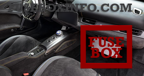
Passenger compartment fuse box location:

The fuse box is located under the passenger's footrest, under the dashboard.
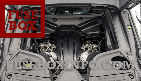
Engine compartment fuse box locatiom:

Luggage compartment fuse box location:

Fuse Box Diagram | Layout
Passenger compartment fuse box:
| Fuse/Relay N° | Rating | Functions |
| 33 | 25A | Front Driver Window Lifter |
| 34 | 25A | Front Passenger Window Lifter |
| 36 | 15A | HVAC, ASU, HFSU, EPB switch, RFHM, KNOB, plafoniera, TBM, EOBD, EMC, SGW and DCSD module |
| 37 | 10A | IPC module |
| 38 | 20A | Lock/Unlock Fuel Lid and Latch-Liftgate |
| 42 | 7.5A | BSM, EPS and CDCM module |
| 43 | 20A | Output from relay Washer pump |
| 49 | 7.5A | PAM, Blindspot, Internal mirror and lifter |
| 50 | 7.5A | ORC |
| 51 | 7.5A | AC Compressor, HVAC, Air quality sensor, T09 internal relay FDU, Humidity sensor, RVDM |
| 53 | 7.5A | Clockspring, start button and IPC |
Engine compartment fuse box:
| Fuse/Relay N° | Rating | Functions |
| 03 | 20A | Direct starter control |
| 04 | 20A |
A/C Fans
|
| 07 | 50A |
Main Relay
|
| 14 | 15A |
Direct battery positive TCM
|
| 16 | 5A |
Ignition switch output ECM-TCM
|
| 18 | 10A |
E-LATCH Driver
|
| 19 | 10A |
E-LATCH Passenger
|
| 22 | 10A |
A/C Compressor
|
| 24 | 20A |
Primary loads NCM Master
|
| 82 | 30A |
Fuel pump 2
|
| 83 | 30A |
Fuel pump 1
|
| 84 | 7.5A |
Direct battery positive ECM
|
| 87 | 25A |
ECM module
|
| 89 | 20A |
Electrical water pump
|
| 90 | 5A |
ELDOR battery
|
| FXX | 20A |
Secondary Loads
|
| T07 | 50A |
Main Relay
|
| T09 | 30A |
A/C Compressor
|
| T17 | 30A |
Electrical water pump
|
| R1 | 30A |
Pump 2 Realy
|
| R2 | 30A |
BCM relay
|
| F01 | 15A |
Engine secondary loads
|
| R1 | 30A |
Pump 1 Realy
|
| R2 | 30A |
Starter relay
|
| F01 | 20A |
Engine primary loads NCM slave
|
| C038 D | 30A |
Engine A/C fans
|
Luggage compartment fuse box:
| Fuse/Relay N° | Rating | Functions |
| 01 | 50A | Main Roof |
| 02 | 20A | ECU Chassis Domain Control input |
| 03 | 30A | Hi-Fi 2 relay input |
| 06 | 30A | ETM R1 relay input |
| 07 | 40A | HVAC front blower relay coil |
| 08 | 30A | Hi-Fi 1 relay input |
| 09 | 20A | RH seat movement |
| 10 | 15A | Horn input |
| 14 | 7.5A | External Mirror input |
| 17 | 5A | Wireless charger |
| 18 | 10A | LH seat movement |
| 19 | 7.5A | ECU Chassis Domain Control input |
| 20 | 20A | Power Outlet Trunk input |
| 21 | 10A | Dna/Hub usb ports |
| 23 | 25A | LH seat movement + Heated seats |
| 82 | 20A | BCM key relays |
| 83 | 20A | Wiper |
| 84 | 7.5A | ECU Lifter input |
| T07 | 50A | HVAC front blower relay coil |
| T09 | 30A | Wireless charger input |
| Next fuses boxes are located in the front luggage compartment, but are not accessible by the user. | ||
| R1 | 30A | Horn relay input |
| R3 | 30A | ECU Chassis Domain Control input |
| 01 | 125A | FDU input |
| 02 | 80A | EPS |
| 03 | 100A | Enable cooling fan relay input |
| 04 | 70A | IBS - MKC1 |
| 05 | 40A | IBS - Valves |
| 06 | 50A | Lifter input |
| P035 | 5A | Battery charge status sensor |
| C038 | 50A | Lifter pump relay |
| P059 | 2A | Clockspring input |


