Aston Martin DB11 2018 Fuse Box Info
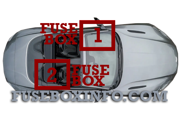
Passenger compartment fuse box location:

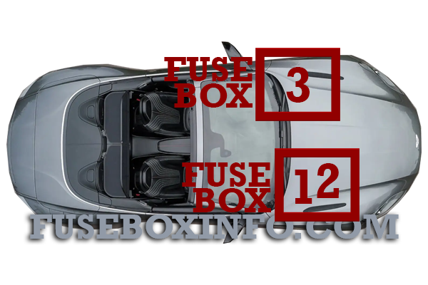
Engine compartment fuse box location:

Fuse Box Diagram | Layout
Passenger compartment fuse box 1 (Fuse panel B):
| Fuse/Relay N° | Rating | Functions |
| Fuse panel B | ||
| 1 | 10A | Control Dial, Touch Pad, Instrument Cluster Fan |
| 2 | 15A | HVAC Module |
| 3 | 5A | Instrument Cluster |
| 4 | 15A | OBD Socket |
| 5 | 20A | Infotainment Unit |
| 6 | 5A | SCCM |
| 7 | 20A | Drive Unit |
| 8 | 5A | Tracker |
| 9 | 7.5A | Steering Column Control Module (SCCM) |
| 10 | 15A | Common Powertrain Control (CPC) module |
| 11 | 5A | Centre Stack Panel |
| 12 | 5A | CPC module |
| 13 | 7.5A | Central Display |
| 14 | 10A | OBD Socket |
| 15 | 20A | Electronic Steering Lock |
| 16 | 5A | Feedback signal to Body Controller - Front (BCF) |
Passenger compartment fuse box 2 (Fuse panel G, H, I, J, K):
| Fuse/Relay N° | Rating | Functions |
| Fuse panel G | ||
| 1 | 50A | IP Fuse box (B) Supply |
| 2 | 50A | IP Fuse box (B) Supply |
| 3 | 50A | Fuse Box (K) Supply |
| 4 | 50A | Fuse Box (K) Supply |
| 5 | 60A | Fuse Box (K) Supply |
| 6 | 30A | Right Side Door Module |
| 7 | 30A | Left side Door Module |
| 8 | 40A | Body Controller Rear(BCR) |
| 9 | 40A | BCR |
| 10 | 40A | Body Controller Front (BCF) |
| 11 | 40A | BCF |
| 12 | 50A | Fuse Box (I) Supply |
| 13 | 30A | IP Fuse box (B) Supply |
| 14 | 20A | Fuse Box (I) Supply |
| Fuse panel H | ||
| 1 | 50A | IP Fuse box (B) Supply |
| 2 | 40A | Fuse Box (J) Supply |
| 3 | 50A | Fuse Box (J) Supply |
| 4 | 50A | Fuse Box (J) Supply |
| 5 | 50A | Fuse Box (J) Supply |
| 6 | - | - |
| 7 | 30A | Heated Rear Window |
| 8 | - | - |
| 9 | - | - |
| 10 | - | - |
| 11 | - | - |
| 12 | 20A | Forward Harness Supply |
| 13 | 40A | Amplifier |
| 14 | 60A | HVAC Blower |
| Fuse panel I | ||
| 1 | 7.5A | Occupant Restraint Controller (ORC) |
| 2 | 5A | - |
| 3 | 10A | Seat Comfort Functions |
| 4 | - | - |
| 5 | - | - |
| 6 | 10A | Blind Spot Monitoring Radar |
| 7 | 5A | Fuel Supply Control Module (FSCM) |
| 8 | 5A | - |
| 9 | 10A | Transmission Control Module (TCM) |
| 10 | - | - |
| 11 | 5A | Feedback signal to Body Controller - Rear (BCR) |
| 12 | 20A | Forward Harness Supply |
| Fuse panel J | ||
| 1 | 10A | Left Side Seat Module |
| 2 | 15A | Camera Module |
| 3 | 15A | TCM |
| 4 | 15A | Left Side Seat Lumbar Adjust |
| 5 | - | - |
| 6 | 5A | Multimedia Box |
| 7 | 5A | Tuner Box |
| 8 | 15A | Right Side Seat Lumbar Adjust |
| 9 | 5A | Body Controller |
| 10 | 25A | Adaptive Damping Module |
| 11 | 10A | Right Side Seat Module |
| 12 | 5A | Rain/Light Sensor |
| 13 | 5A | Park Distance Control |
| 14 | 5A | Amplifier (non B&O) |
| 15 | 7.5A | Overhead Module |
| 16 | 5A | Brake Pedal Sensor |
| Fuse panel K | ||
| 1 | 10A | Microwave Sensors |
| 2 | 7.5A | ORC |
| 3 | 5A | Ignition/accessory Relay Control |
| 4 | 25A | Right Side Seat Module |
| 5 | 5A | Keyless Go Module |
| 6 | 20A | Charger Port |
| 7 | 25A | Left Side Seat Module |
| 8 | 5A | Deck Lid Latch |
| 9 | 25A | Fuel Supply Control Module (FSCM) |
| 10 | 25A | 12V Accessory Socket |
| 11 | 15A | Centre Stack Panel |
| 12 | 20A | Deployable Spoiler |
Engine compartment fuse box 1 (Fuse panel A):
| Fuse/Relay N° | Rating | Functions |
| Fuse panel A | ||
| V12 Engine | ||
| 1 | 150A | Electronic Power Assisted Steering (EPAS) |
| 2 | 100A | Cooling Fan |
| 3 | 150A | Right Side Engine Fuse Box |
| 4 | 50A | ABS Module |
| 5 | 100A | Left Side Powerhold Fuse Box |
| 6 | 100A | Right Side Powerhold Fuse Box |
| 7 | 100A | Left side Engine Fuse Box |
| 8 | 100A | Left side Engine Fuse Box |
| V8 Engine | ||
| 1 | 150A | Electronic Power Assisted Steering (EPAS) |
| 2 | 100A | Cooling Fan |
| 3 | 150A | Right Side Engine Fuse Box |
| 4 | 50A | ABS Module |
| 5 | 100A | Right Side Engine Fuse Box |
| 6 | 100A | Right Side Powerhold Fuse Box |
| 7 | 100A | Right Side Powerhold Fuse Box |
| 8 | 100A | Left Side Powerhold Fuse Box |
Engine compartment fuse box 2 (Fuse panel C, D):
| Fuse/Relay N° | Rating | Functions |
| Fuse panel C | ||
| V12 Engine | ||
| 1 | - | - |
| 2 | - | - |
| 3 | - | - |
| 4 | - | - |
| 5 | 10A | HEGO Sensor Bank A, Catalyst Monitor Bank A |
| 6 | 20A | Coolant water pump A, Central Fan Module |
| 7 | 5A | Oil Level Sensor, Mass Air Flow (MAF) Sensor A, Cannister Purge A, Starter Relay, Secondary Air Relay A |
| 8 | 10A | - |
| 9 | 20A | Fuel Injectors Bank A |
| 10 | 15A | Ignitions Coils Bank A |
| 11 | 10A | Variable Cam Timing (VCT) unit A, Compressor Valve A, Secondary Air Injector A, Variable Oil Pump, Coolant Pump Run On |
| 12 | 15A | Differential Cooling Pump |
| V8 Engine | ||
| 1 | - | - |
| 2 | - | - |
| 3 | - | - |
| 4 | - | - |
| 5 | - | - |
| 6 | 20A | Coolant water pump B |
| 7 | 20A | Cooling Fan |
| 8 | 20A | Coolant water pump A |
| 9 | 25A | Engine Supply |
| 10 | 25A | Engine Supply |
| 11 | 10A | Purge Valve A, Purge Valve B |
| 12 | 15A | Differential Cooling Pump |
| Fuse panel D | ||
| V12 Engine | ||
| 1 | 5A | ECM Keep Awake |
| 2 | 15A | Right Side Powerhold Supply |
| 3 | 5A | Right Side Powerhold Control |
| 4 | 5A | ABS Module |
| 5 | 30A | Right Side Wiper Motor |
| 6 | 40A | ABS Module |
| 7 | 40A | Secondary Air Pump A |
| 8 | - | - |
| 9 | 30A | Starter Motor |
| 10 | 15A | Horn |
| 11 | 5A | Bonnet Latches |
| 12 | - | - |
| V8 Engine | ||
| 1 | 5A | ECM Keep Awake |
| 2 | 15A | Right Side Powerhold Supply |
| 3 | 5A | ABS Module |
| 4 | 30A | Starter Motor |
| 5 | 30A | Left Side Wiper Motor |
| 6 | 30A | Right Side Wiper Motor |
| 7 | 5A | Relay Tracker |
| 8 | 40A | ABS Module |
| 9 | - | - |
| 10 | 15A | Horn |
| 11 | 5A | Bonnet Latches |
| 12 | - | - |
Engine compartment fuse box 3 (Fuse panel E, F):
| Fuse/Relay N° | Rating | Functions |
| Fuse panel E | ||
| V12 Engine | ||
| 1 | 5A | ECM Keep Awake |
| 2 | 15A | Left Side Powerhold Supply |
| 3 | 5A | Left Side Powerhold Control |
| 4 | 5A | Tracker |
| 5 | 30A | Left Side Wiper Motor |
| 6 | 40A | Secondary Air Pump B |
| 7 | - | - |
| 8 | - | - |
| 9 | 40A | Vacuum Pump |
| 10 | - | - |
| 11 | - | - |
| 12 | 5A | Vacuum Pump Monitor |
| V8 Engine | ||
| Not Applicable | ||
| Fuse panel F | ||
| V12 Engine | ||
| 1 | 5A | ABS Module |
| 2 | 5A | Engine Control Module Wake up |
| 3 | 5A | Tyre Pressure Monitoring System (TPMS) |
| 4 | 15A | Daytime Running Lights |
| 5 | 10A | HEGO Sensor Bank B, Catalyst Monitor Bank B |
| 6 | 20A | Coolant water pump Bank B |
| 7 | 10A | Engine Coolant Level Sensor, MAF Bank B, Cannister Purge B, Secondary Air Relay B |
| 8 | 15A | Exhaust Flaps |
| 9 | 20A | Fuel Injectors Bank B |
| 10 | 15A | Ignitions Coils Bank B |
| 11 | 10A | VCT Bank B, Compressor Valve B, Secondary Air Injector B |
| 12 | 10A | Sound regulator |
| V8 Engine | ||
| 1 | 5A | ABS Module |
| 2 | 5A | Engine Control Module Wake up |
| 3 | 5A | Tyre Pressure Monitoring System (TPMS) |
| 4 | 15A | Daytime Running Lights |
| 5 | 10A | Engine Supply |
| 6 | 20A | Engine Supply |
| 7 | - | - |
| 8 | 15A | - |
| 9 | - | - |
| 10 | 15A | - |
| 11 | - | - |
| 12 | - | - |


