Ford Escape Hybrid 2008 Fuse Box Info
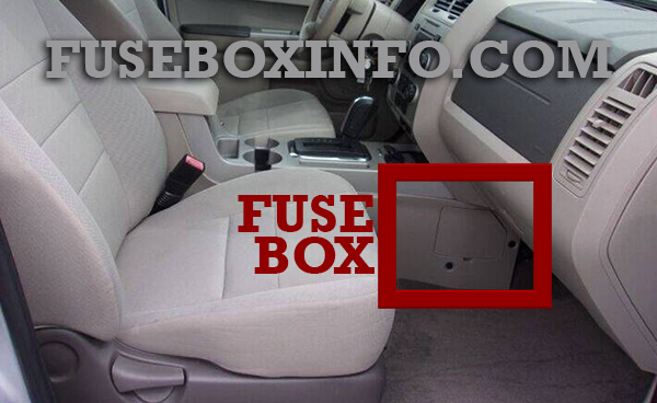
Passenger compartment fuse box location:

The fuse box is located on the right-hand side of the center console, by the instrument panel.
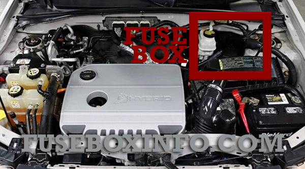
Engine compartment fuse box location:

Fuse Box Diagram | Layout
Passenger compartment fuse box:
| Fuse/Relay N° | Rating | Functions |
| 1 | 30A | 110V inverter |
| 2 | 15A | Brake On/Off switch |
| 3 | 15A | Not used (spare) |
| 4 | 30A | Not used (spare) |
| 5 | 10A | Brake Shift Interlock (BSI), SPDJB, Keypad illumination |
| 6 | 20A | Turn signals, Stop lamps |
| 7 | 10A | Low beam headlamps (left) |
| 8 | 10A | Low beam headlamps (right) |
| 9 | 15A | Interior lights |
| 10 | 15A | Backlighting |
| 11 | 10A | Four wheel drive |
| 12 | 7.5A | Power mirror switch |
| 13 | 7.5A | Canister vent |
| 14 | 10A | FCIM (radio buttons), Satellite radio, Front display module |
| 15 | 10A | Climate control |
| 16 | 15A | Not used (spare) |
| 17 | 20A | All lock motor feeds, Liftgate release, Liftglass release |
| 18 | 20A | Heated seat |
| 19 | 25A | Rear wiper |
| 20 | 15A | Datalink |
| 21 | 15A | Fog lamps |
| 22 | 15A | Park lamps |
| 23 | 15A | High beam headlamps |
| 24 | 20A | Horn relay |
| 25 | 10A | Demand lamps |
| 26 | 10A | Instrument panel cluster |
| 27 | 20A | Ignition switch |
| 28 | 5A | Radio |
| 29 | 5A | Instrument panel cluster |
| 30 | 5A | Not used (spare) |
| 31 | 10A | Restraints control module |
| 32 | 10A | Not used (spare) |
| 33 | 10A | Not used (spare) |
| 34 | 5A | Speed control deactivate switch, ABS |
| 35 | 10A | Four wheel drive, EPAS (steering), 110V inverter module, Park aid module |
| 36 | 5A | PATS transceiver |
| 37 | 10A | Climate control |
| 38 | 20A | Subwoofer/Amp (Audiophile radio) |
| 39 | 20A | Radio |
| 40 | 20A | Front power point |
| 41 | 15A | Driver/passenger door lock switches, Auto dimming mirror, Compass, Ambient lighting |
| 42 | 10A | Not used (spare) |
| 43 | 10A | Rear wiper logic, Heated seats relay, Instrument cluster |
| 44 | 10A | Not used (spare) |
| 45 | 5A | Front wiper logic, Blower motor relay |
| 46 | 7.5A | OCS (restraints), PADI (restraints) |
| 47 | 30A | Power windows, Moon roof |
| 48 | - | Delayed accessory relay |
Engine compartment fuse box:
| Fuse/Relay N° | Rating | Functions |
| A | 80A | Power steering control module |
| B | 125A | PDB |
| 1 | 15A | Heated mirror |
| 2 | 30A | Rear defroster |
| 3 | 20A | Rear power point |
| 4 | 20A | Fuel injector |
| 5 | 10A | Powertrain Control Module (PCM) Keep Alive power, TBCM |
| 6 | 5A | Anti-lock Brake System (ABS) |
| 7 | 10A | Reverse lamps |
| 8 | 5A | Transaxle Control Module (TCM) |
| 9 | 50A | ABS |
| 10 | 30A | Front wipers |
| 11 | 30A | PCM/Power sustain |
| 12 | 40A | Blower motor |
| 13 | 10A | A/C clutch |
| 14 | 10A | Heater/Coolant pump |
| 15 | 50A | Traction Battery Control Module (TBCM) |
| 16 | 40A | Cooling fan 1 |
| 17 | 40A | Cooling fan 2 |
| 18 | 50A | ABS solenoid |
| 19 | 30A | Power seats |
| 20 | - | A/C clutch relay |
| 21A | - | Rear defroster relay |
| 21B | - | Not used |
| 21C | - | Blower relay |
| 21D | - | PCM relay |
| 22 | - | Not used |
| 23 | 5A | TBCM |
| 24 | 20A | Fuel pump |
| 25 | 15A | Ignition coils |
| 26 | 5A | TBCM |
| 27 | 10A | Cooling fan/TCM |
| 28 | 15A | Heated Exhaust Gas Oxygen (HEGO) sensor |
| 29 | 15A | PCM power |
| 30A | - | Cooling fan 1 relay |
| 30B | - | Power sustain relay |
| 30C | - | Cooling fan main relay |
| 30D | - | Cooling fan 2 relay |
| 31A | - | Reverse lamp relay |
| 31B | - | Injector relay |
| 31C | - | Heater pump relay |
| 31D | - | Coolant pump relay |
| 31E | - | Not used |
| 31F | - | Not used |
| 32 | - | A/C clutch diode |
| 33 | - | PCM diode |
| 34 | - | Not used |
| 35 | 5A | RUN/START |
| 36 | - | Not used |
| 37 | - | Not used |


