
Ford Mustang 2005 Fuse Box Info
Fuse box location:
The fuse panel is located in the passenger side kick panel. Remove the panel cover to access the fuses.
Engine compartment fuse box:
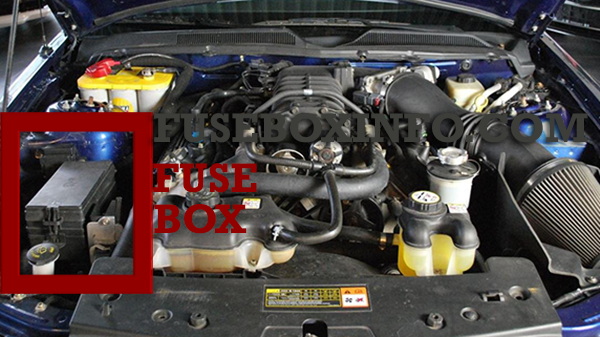
The fuse box is in the front right of the engine compartment.
Fuse Box Diagram | Layout
Passenger compartment fuse box:
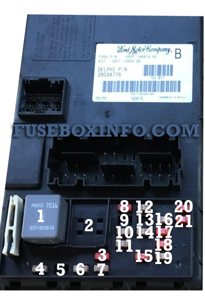
| Fuse/Relay N° | Rating | Functions |
| 1 | Mini relay | Accessory delay #1 |
| 2 | - | Not used |
| 3 | 10 A | Wiper power |
| 4 | 5 A | Power mirrors |
| 5 | - | Not used |
| 6 | 5 A | Accessory delay feeds |
| 7 | 5 A | Overdrive cancel |
| 8 | 10 A | Cluster, Data Link Connector (DLC) |
| 9 | - | Not used |
| 10 | 5 A | Intrusion Sensing Module (ISM), Climate control |
| 11 | - | Not used |
| 12 | 5 A | Climate control, Ignition |
| 13 | - | Not used |
| 14 | 5 A | A/C cycle switch |
| 15 | 10 A | Brake On/Off (BOO) power |
| 16 | 5 A | Cluster |
| 17 | 10 A | Restraint Control Module (RCM), Passenger Occupant Detection System (PODS), Passenger Air bag Deactivation Indicator (PADI) |
| 18 | 10 A | Anti-lock Brake System (ABS), Positive Crankcase Ventilation (PCV) valve heater, Ignition |
| 19 | 5 A | Powertrain Control Module (PCM) relays, Passive Anti-Theft System (PATS) |
| 20 | 10 A | Radio (Start) |
| 21 | 10 A | Starter relay |
Engine compartment fuse box:
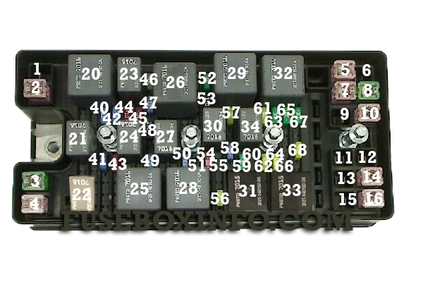
| Fuse/Relay N° | Rating | Functions |
| 1 | - | Not used |
| 2 | 30 A* | Climate control blower |
| 3 | 40 A* | Cooling fan |
| 4 | 30 A* | Starter |
| 5 | 30 A* | Right front window motor |
| 6 | 30 A* | Rear amplifier (Shaker 1000 radio) |
| 7 | 30 A* | Left front window motor |
| 8 | 40 A* | Anti-lock Brake System (ABS) #1 |
| 9 | 30 A* | Rear amplifier (Shaker 1000 radio) |
| 10 | 30 A* | Wipers |
| 11 | 30 A* | Left rear window motor (Convertible only) |
| 12 | 30 A* | Right rear window motor (Convertible only) |
| 13 | 30 A* | Convertible top |
| 14 | 30 A* | Seat |
| 15 | - | Not used |
| 16 | 30 A* | Front amplifier (Shaker 500 radio) |
| 20 | Mini relay | PCM #2 |
| 21 | Micro relay | Fuel pump |
| 22 | Mini relay | Starter |
| 23 | Micro relay | PCM #1 |
| 24 | Micro relay | A/C clutch |
| 25 | Mini relay | Cooling fan (High-speed) |
| 26 | Mini relay | Horn |
| 27 | Micro relay | High beams |
| 28 | Mini relay | Cooling fan (Low-speed) |
| 29 | Mini relay | Rear defroster |
| 30 | Micro relay | Fog lamps |
| 31 | Mini relay | Convertible top (Up) |
| 32 | Mini relay | Climate control blower |
| 33 | Mini relay | Convertible top (Down) |
| 34 | - | Not used |
| 35 | - | Not used |
| 36 | - | Not used |
| 37 | - | Not used |
| 38 | - | Not used |
| 39 | - | Not used |
| 40 | 15 A** | Engine #2 |
| 41 | 15 A** | Fuel pump |
| 42 | 15 A** | Engine #3 |
| 43 | 10 A** | Alternator |
| 44 | 10 A** | Delayed accessory |
| 45 | 10 A** | PCM |
| 46 | 25 A** | Horn |
| 47 | 15 A** | Engine #1 |
| 48 | Diode | A/C clutch |
| 49 | 15 A** | A/C clutch |
| 50 | 15 A** | High beams |
| 51 | 10 A** | Convertible top |
| 52 | 30 A** | Rear defroster |
| 53 | Diode | PCM |
| 54 | 10 A** | PCM delay |
| 55 | - | Not used |
| 56 | 20 A** | Radio |
| 57 | 20 A** | Decklid release |
| 58 | 15 A** | Fog lamps |
| 59 | 30 A** | SJB #5 (Instrument panel fuse box) |
| 60 | - | Not used |
| 61 | 20 A** | Power point #1 (Instrument panel) |
| 62 | 20 A** | SJB #7 (Instrument panel fuse box) |
| 63 | 30 A** | SJB #6 (Instrument panel fuse box) |
| 64 | 20 A** | Power point #2 (Console) |
| 65 | 30 A** | ABS #2 |
| 66 | - | Not used |
| 67 | 30 A** | SJB #4 (Instrument panel fuse box) |
| 68 | 20 A** | Ignition |
|
* Cartridge Fuses ** Mini Fuses |
Auxiliary relay
There is a relay located on the accelerator pedal assembly for the PCM delay. Note: Only on manual transmission applications.