
Dodge Challenger 2012 Fuse Box Info
Luggage fuse box location:

The interior fuse box is located in the rear compartment under the spare tire access panel.
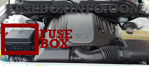
Engine compartment fuse box:
Fuse Box Diagram | Layout
Luggage compartment fuse box:
| Fuse/Relay N° | Rating | Functions |
| 1 | 60A | Ignition Off Draw (IOD) |
| 2 | 40A | Integrated Power Module (IPM) |
| 3 | - | - |
| 4 | 40A | Integrated Power Module (IPM) |
| 5 | 30A | Heated Seats - if equipped |
| 6 | 20A | Fuel Pump |
| 7 | 15A | Audio Amplifier – If Equipped |
| 8 | 15A | Diagnostic Link Connector (DLC)/ Wireless Control Module (WCM)/ Wireless Ignition Node (WIN) |
| 9 | 20A | Power Outlet |
| 10 | 25A | Vacuum Pump – If Equipped |
| 11 | - | - |
| 12 | - | - |
| 13 | - | - |
| 14 | 10A | AC Heater Control/ Cluster/Security Module - if equipped |
| 15 | 20A | Active Damper – If Equipped |
| 16 | 20A | Heated Seat Module – If Equipped |
| 17 | 20A | Instrument Cluster |
| 18 | 20A | Cigar Lighter (Instrument Panel) |
| 19 | 10A | Stop Lights |
| 20 | - | - |
| 21 | - | - |
| 22 | - | - |
| 23 | - | - |
| 24 | - | - |
| 25 | - | - |
| 26 | - | - |
| 27 | 10A | Occupant Restraint Controller (ORC) |
| 28 | 10A | Ignition Run, AC Heater Control/Occupant Restraint Controller (ORC) |
| 29 | 5A | Cluster/Electronic Stability Program (ESP)/Powertrain Control Module (PCM)/STOP LIGHT Switch |
| 30 | 10A | Door Modules/Power Mirrors/Steering Control Module (SCM) |
| 31 | - | - |
| 32 | - | - |
| 33 | - | - |
| 34 | - | - |
| 35 | 5A | Antenna Module - if equipped/Power Mirrors |
| 36 | 25A | Hands-Free Phone - if equipped/Radio/ Amplifier Feed |
| 37 | 15A | Transmission |
| 38 | 10A | Cargo Light/Vehicle Information Module - if equipped |
| 39 | 10A | Heated Mirrors - if equipped |
| 40 | 5A | Auto Inside Rearview Mirror/Heated Seats - if equipped/Switch Bank |
| 41 | - | - |
| 42 | 30A | Front Blower Motor |
| 43 | 30A | Rear Window Defroster |
| 44 | 20A | Amplifier/Sunroof - if equipped |
Engine compartment fuse box:
| Fuse/Relay N° | Rating | Functions |
| 1 | 15A | Washer Motor |
| 2 | 25A | Powertrain Control Module (PCM) |
| 3 | 25A | Ignition Run/Start |
| 4 | 25A | EGR Solenoid/ Alternator |
| 5 | 15A | Powertrain Control Module |
| 6 | 25A | Ignition Coils/Injectors |
| 7 | 25A | Headlamp Washer Relay – If Equipped |
| 8 | 25A | Starter |
| 9 | - | - |
| 10 | 30A | Windshield Wiper |
| 11 | 30A | Anti-Lock Brake System (ABS) Valves |
| 12 | 40A | Radiator Fan Lo/High |
| 13 | 50A | Anti-Lock Brake System (ABS) Pump Motor |
| 14 | - | Spare |
| 15 | 50A | Radiator Fan Motor |
| 16 | - | - |
| 17 | - | - |
| 18 | - | - |
| 19 | - | - |
| 20 | - | - |
| 21 | - | - |
| 22 | - | - |