
Chevrolet Colorado 2026 Fuse Box Info
Passenger compartment fuse box location:
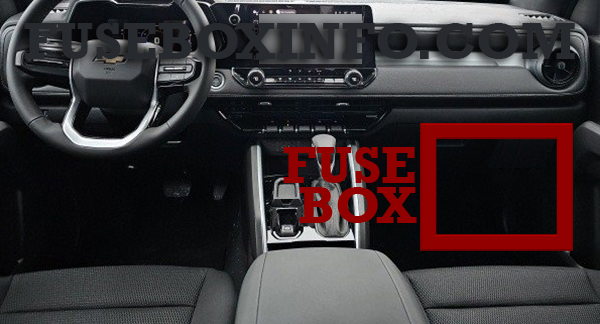
The instrument panel fuse box is located behind a side trim panel.
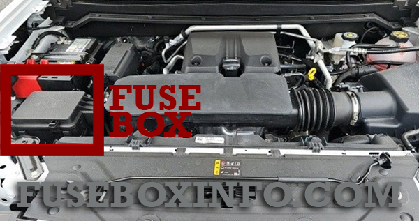
Engine compartment fuse box location:
Fuse Box Diagram | Layout
Passenger compartment fuse box:
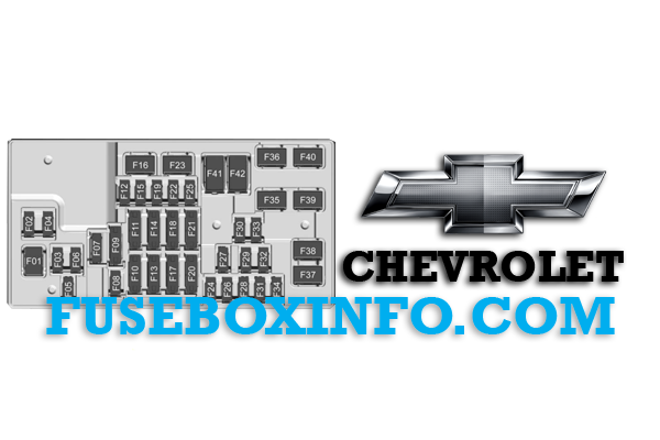
| Fuse/Relay N° | Functions |
| 01 | FRONT HVAC BLOWER – Front HVAC Module |
| 02 | ELM 1 – Exterior Lighting Module 1 |
| 03 | TRANS CNTRL MODULE – Transmission Control Module |
| 04 | ELM 2 – Exterior Lighting Module 2 |
| 05 | DRIVER SEAT MISC – Memory Seat Module/Seat Position Switch |
| 06 | BODY CNTRL MODULE 1 – Body Control Module 1 |
| 07 | STR/WHL/CNTRLS – Steering Wheels Controls |
| 08 | - |
| 09 | - |
| 10 | MISCELLANEOUS 1 Electric Park Break Switch (EPBS)/Automatic Occupant Sensing Display (AOSD)/SPARE |
| 11 | AUX JACK – Auxiliary Audio/Video Jack ONSTAR – OnStar Telematics Control Platform Module (TCP) |
| 12 | - |
| 13 | CGM-SDM – Central Gateway Module-Sensing Diagnostic Module AOS – Automatic Occupant Sensing Module |
| 14 | MISCELLANEOUS 2 Transmission Control Module (TCM)/Transfer Case Control Module (TCCM)/Electronic Brake Control Module (EBCM)/Integrated Chassis Control Module (ICCM)/Trailer Interface Module (TIM)/SPARE |
| 15 | MISCELLANEOUS 3 – Exterior Lighting Module (ELM)/Direct Current-Alternating Current Inverter Module (DC/AC)/Seat Fan Control Cushion Module (Vented Mod) |
| 16 | - |
| 17 | WCM – Wireless Charger Module DATA LINK CONN – Data Link Connector (DLC) |
| 18 | MISCELLANEOUS 4 – E-Stop/Driver Mode Switch (DRV)/Reflective Light Auxiliary Display (RLAD)/Sensing and Diagnostic Module (SDM)/Inside Rear View Mirror (ISRVM)/Humidity Sensor |
| 19 | ENGINE CNTRL MODULE Engine Control Module Run/Crank (ECM) |
| 20 | RFA – Remote Function Receiver Module RPA – Park Assist Module |
| 21 | MISC 1 DISPLAYS – Head Up Display (HUD)/HVAC Display/Instrument Panel Display (IPD)/Virtual Cockpit Display (VCD) VPM – Video Processor Module |
| 22 | SUNROOF – Sunroof Motor (SRC) |
| 23 | - |
| 24 | TRLR BRK CNTRL SW – Trailer Break Control Switch (TBCS) |
| 25 | AUX USB FLOOR CNSL Auxiliary USB Power Outlet (APO USB) |
| 26 | BODY CNTRL MODULE 2– Body Control Module 2 (BCM) |
| 27 | DOOR PANEL SW LF– Driver Door Switch Panel and Power Window Regulator (Express Up/Down)/Passenger Power Window Regulator (Express Up/Down) |
| 28 | BODY CNTRL MODULE 3 – Body Control Module 3 |
| 29 | ELM 3 – Exterior Lighting Module 3 |
| 30 | FRONT CAMERA – Front Camera Module (FCM) |
| 31 | VCU MDL – Virtual Cockpit Unit Module |
| 32 | HTD STR WHL – Heated Steering Wheel Module |
| 33 | ELM 5 – Exterior Lighting Module 5 |
| 34 | BODY CNTRL MODULE 4– Body Control Module 4 (BCM) |
| 35 | DC/DC CONVERTER 2 – Direct Current/Direct Current Converter Module Batt 2 |
| 36 | DC/DC CONVERTER 1 – Direct Current/Direct Current Converter Module Batt 1 |
| 37 | FRT SEATS LMBR SWS – Front Seat Lumbar Switches |
| 38 | - |
| 39 | DRIVER POWER SEAT – Driver Power Seat Switch/Memory Seat Module |
| 40 | PASSENGER POWER ST– Passenger Seat Position Switch |
| 41 | APO CONSOLE – Auxiliary Direct Current Power Outlet |
| 42 | - |
Engine compartment fuse box:
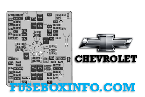
| Fuse/Relay N° | Functions |
| 01 | ICCM – Integrated Chassis Control Module |
| 02 | FUEL TANK ZONE MDL – Fuel Tank Zone Module |
| 03 | - |
| 04 | Cooling Fan 2 |
| 05 | - |
| 06 | - |
| 07 | MTAOP – Transmission Auxiliary Oil Pump Motor |
| 08 | - |
| 09 | - |
| 10 | - |
| 11 | SECONDARY AXLE MTR – Front Drive Axle Actuator |
| 12 | - |
| 13 | Trailer Connector |
| 14 | - |
| 15 | SBZA/CVS – Side Blind Zone Alert/Canister Vent Solenoid |
| 16 | - |
| 17 | - |
| 18 | - |
| 19 | EBCM 1 – Electronic Brake Control Module 1 |
| 20 | Cooling Fan 1 |
| 21 | - |
| 22 | - |
| 23 | - |
| 24 | Cooling Fan 3 |
| 25 | ENG MISC 1/ENG MISC 2– Wide Range Air Fuel Oxygen Sensor/Canister Purge/Turbo Bypass/Step Cam Intake-Exhaust Solenoids/Block Coolant Valve Actuator/Mass Air Flow/Humidity/Induction Air Temperature/Throttle Inlet Pressure Sensors |
| 26 | A/C CLUTCH – Air Compressor Clutch |
| 27 | Park Lamps |
| 28 | TIM 2 – Trailer Interface Module 2 |
| 29 | Spare |
| 30 | - |
| 31 | POWER TRAIN IGN 1 – Power Train Ignition 1 |
| 32 | - |
| 33 | TRLR REVERSE LAMPS Trailer Reverse Lights/Spare |
| 34 | TIM 1 – Trailer Interface Module 1 |
| 35 | Service Fuse |
| 36 | ENGINE CONTROL MDL – Engine Control Module |
| 37 | IGNITION COILS |
| 38 | TRLR STOP LAMP LT – Trailer Stop Lamp Left |
| 39 | TRLR STOP LAMP RT – Trailer Stop Lamp Right |
| 40 | TCCM – Transfer Case Control Module |
| 41 | Starter Pinion |
| 42 | Starter |
| 43 | - |
| 44 | Service Fuse |
| 45 | Service Fuse |
| 46 | Service Fuse |
| 47 | Service Fuse |
| 48 | Service Fuse |
| 49 | TBPM/TRLR WRG – Trailer Brake Power Module/Trailer Wiring Provisions |
| 50 | Service Fuse |
| 51 | CHMSL – Center High Mounted Stop Lamp |
| 52 | Side Markers |
| 53 | Service Fuse |
| 54 | - |
| 55 | REAR WNDW DEFOGGER – Rear Window Defogger |
| 56 | - |
| 57 | - |
| 58 | Front Wipers |
| 59 | MISC WINDOWS LEFT Driver Door Panel Switch/Window Motor Left Front/Window Switch Left Rear/Window Motor Left Rear |
| 60 | - |
| 61 | Service Fuse |
| 62 | Amplifier |
| 63 | - |
| 64 | - |
| 65 | ELM 4 – Exterior Lighting Module 4 – Right Front Park Light/Daytime Running Light/Left Trailer Stop/Turn Light/Left Rear Park Light/Right High Beam |
| 66 | LOW BEAMS – Front LED Low Beams Left/Right |
| 67 | - |
| 68 | HTD ST MDL 1 – Heated Seat Module 1 – Front Heated Seats |
| 69 | U/B CAMERA WASHER – Underbody Camera Washer |
| 70 | - |
| 71 | DC/AC INVERTER – Direct Current to Alternate Current Inverter |
| 72 | Service Fuse |
| 73 | Aeroshutter |
| 74 | ELM 6 – Exterior Lighting Module 6 – Left Low Beam/Right Rear Stop/Turn Light |
| 75 | Service Fuse |
| 76 | HTD ST MDL 2 – Heated Seat Module 2 – Front Heated Seat |
| 77 | - |
| 78 | - |
| 79 | - |
| 80 | - |
| 81 | - |
| 82 | - |
| 83 | LED Cargo Lamp |
| 84 | ELM 7 – Exterior Lighting Module 7 – Left Front Park Light/Daytime Running Light/Left Front Turn Light/Center High Mounted Stop Light/Right Rear Park Light/Reverse Lights |
| 85 | - |
| 86 | Horn |
| 87 | Front Washer Pump |
| 88 | - |
| 89 | - |
| 90 | MISC WINDOWS RIGHT–Passenger Door Panel Switch/Window Motor Right Front/Window Switch Right Rear/Window Motor Right Rear |
| 91 | - |
Accessory fuse box (near the battery in the engine compartment) - If equipped:
| Fuse/Relay N° | Functions |
| Fuses | |
| F01 | AUX – Center Stack Auxiliary Switch 6 |
| F02 | AUX 1– Auxiliary Switch 1 |
| F03 | AUX 2– Auxiliary Switch 2 |
| F04 | AUX 3– Auxiliary Switch 3 |
| F05 | - |
| F06 | - |
| Relays | |
| K01 | AUX – Center Stack Auxiliary Switch 6 |
| K02 | AUX 1– Auxiliary Switch 1 |
| K03 | AUX 2– Auxiliary Switch 2 |
| K04 | AUX 3– Auxiliary Switch 3 |
| K05 | - |
| K06 | - |