Chevrolet Spark 2022 Fuse Box Info
Passenger compartment fuse box location:
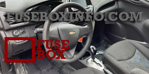
The instrument panel fuse box is on the underside of the driver side instrument panel.
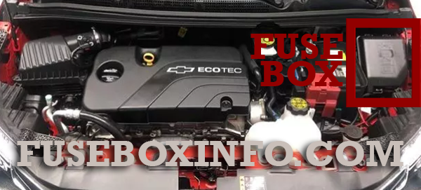
Engine compartment fuse box location:
Fuse Box Diagram | Layout
Passenger compartment fuse box:
| Fuse/Relay Name | Functions |
| ONSTAR | OnStar |
| HVAC CNTR/ECC | HVAC Control Module/ Electronic Climate Control |
| IPC | Instrument cluster |
| TCM | Transmission control module |
| RDO | Radio |
| BCM1 (AT S&S) |
Body control module 1 (CVT stop and start) |
| SBSA/RPA | Side Blind Spot Alert/ Rear Park Assist |
| DLC | Data link connector |
| ESCL | Electric steering column lock |
| SDM | Sensing and diagnostic module |
| TRANSD | DC-DC converter |
| AQI | Virtual key pass system module |
| ETCS | Electronic toll collection system |
| LPM | Linear power module |
| PEPS | Passive entry/ Passive start |
| DLIS (Non AT S&S) | Discrete logic ignition switch (non-CVT stop and start) |
| FCA | Forward Collision Alert |
| IPC | Instrument cluster |
| RLAD | Reflected LED alert display |
| HLLD SW | Headlamp leveling switch |
| FRT PWR WNDW |
Front power window |
| REAR PWR WNDW |
Rear power window |
| - | - |
| MTA | Automated manual transmission module |
| APO | Auxiliary power outlet |
| S/ROOF | Sunroof |
| CGM | Central gate module |
| - | - |
| BCM8 | Body control module 8 |
| BCM7 | Body control module 7 |
| BCM6 | Body control module 6 |
| BCM5 | Body control module 5 |
| BCM4 | Body control module 4 |
| BCM3 | Body control module 3 |
| BCM2 (Non AT S&S) |
Body control module 2 (non-CVT stop and start) |
| BCM1 (Non AT S&S) |
Body control module 1 (non-CVT stop and start) |
| DLIS (AT S&S) |
Discrete logic ignition switch (CVT stop and start) |
| SWC BKLT | Steering wheel controls backlighting |
| - | - |
| TRANS (200/ 400W)/ LOGISTICS |
DC DC converter/ Logistics |
| EXP PWR WNDW |
Driver express power window |
| BLWR | Blower motor |
| HTD/SEAT | Front heated seats |
| HVAC CNTR | HVAC module |
| HTD/STR | Heated steering wheel |
| BCM2 (AT S&S) |
Body control module 2 (CVT stop and start) |
| RLY1 | Logistics relay |
| RLY2 | Accessory/ Retained accessory power relay |
| RLY3 | Interruptible retained accessory power relay |
| RLY4 | Run relay |
Engine compartment fuse box:
| Fuse/Relay N° | Functions |
| 1 | Liftgate latch |
| 2 | Transmission output speed sensor |
| 3 | Rear defogger |
| 4 | Outside mirror heater |
| 5 | Sunroof |
| 6 | Continuously variable transmission control module |
| 7 | Mass air flow sensor |
| 8 | - |
| 9 | ABS valve |
| 10 | Regulated voltage control |
| 11 | Rear vision camera |
| 12 | - |
| 13 | - |
| 14 | Engine control module/ Transmission control module |
| 15 | Fuel injection control module/ Starter motor |
| 16 | Fuel pump motor |
| 17 | Engine control module 1 |
| 18 | Engine control module 2 |
| 19 | Injector/Ignition |
| 20 | A/C system |
| 21 | Intelligent battery sensor |
| 22 | Electric steering column lock |
| 23 | Cooling fan – low |
| 24 | Virtual key pass system sensor |
| 25 | Outside mirror motor control |
| 26 | Engine control module/ Transmission control module battery |
| 27 | Canister vent solenoid |
| 28 | - |
| 29 | Automatic occupant sensing |
| 30 | Headlamp leveling motor |
| 31 | Horn |
| 32 | Front fog lamps |
| 33 | Left high-beam headlamp |
| 34 | Right high-beam headlamp |
| 35 | Air quality ionizer |
| 36 | Rear wiper |
| 37 | Left cornering lamp |
| 38 | Washer motor |
| 39 | Right cornering lamp |
| 40 | - |
| 41 | Virtual key pass system sensor |
| 42 | Starter 2 |
| 43 | In-panel bussed electrical center |
| 44 | Automated manual transmission |
| 45 | Starter 1 |
| 46 | ABS pump |
| 47 | Cooling fan – high |
| 48 | Front wiper motor |
| 49 | Accessory/ Retained accessory power |
| RLY1 | Rear defogger |
| RLY2 | Transmission control module |
| RLY3 | Fuel pump motor |
| RLY4 | Starter 2 |
| RLY5 | A/C system |
| RLY6 | - |
| RLY7 | Cooling fan – low |
| RLY8 | Run/Crank |
| RLY9 | Powertrain |
| RLY10 | Starter 1 |
| RLY11 | Cooling fan – high |
| RLY12 | Front fog lamps |